Chapter 4: Drawing
Contents
4.1 Introduction to PDF Drawing
Any page of a PDF document contains a set of graphics operators that define the appearance of this page on computer screen, printer or any other device. Some operators define the current graphics state which includes the current color, current line width, etc. Others define lines, shapes, curves and regions of various sorts by their coordinates. Still others display sequences of text characters, etc.
By default, all drawing on a page occurs in the default user coordinate space with the origin in the lower-left corner of the page. The positive x axis extends horizontally to the right, and the positive y axis vertically upwards, as in standard mathematical practice. The length of a unit along both x and y axes is 1/72 inch.
The central notion in PDF drawing is a path, which is a composition of straight and curved line segments which may connect to one another or may be disconnected.
A straight line is defined by two points - the current point and endpoint. A curved path segment is specified as a Cubic Bezier Curve. Such curves are defined by four points: the two endpoints (the current point P0 and the final point P3) and two control points P1 and P2. The curve does not, in general, pass through the control points:
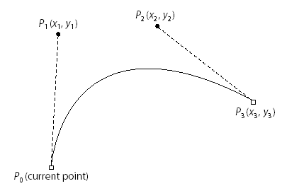
A path is made up of one or more disconnected subpaths, each comprising a sequence of connected segments. Typically, a subpath is defined by specifying its starting point, appending one or more segments to it, and then closing it by appending a straight line segment from the current point to the starting point of the subpath.
Once a path is defined, it is painted by stroking, filling, or both.
4.2 AspPDF.NET's Implementation of Drawing
AspPDF.NET implements drawing functionality via the PdfCanvas object. At least one instance of PdfCanvas is associated with every page and graphics object. To draw on the foreground of a page, the PdfPage.Canvas property is used. To draw on the background, PdfPage.Background is used. Both properties return separate instances of the PdfCanvas object.
The following code segment draws a 5-point star by defining a path made up of a single subpath and stroking it:
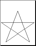
objPage.Canvas.LineTo( 306, 600 );
objPage.Canvas.LineTo( 512, 60 );
objPage.Canvas.LineTo( 20, 400 );
objPage.Canvas.LineTo( 592, 400 );
objPage.Canvas.ClosePath();
objPage.Canvas.Stroke();
A path is started by calling the MoveTo method. A call to LineTo adds a straight line segment to the path. Finally, the path is closed and stroked.
The following code segment draws a propeller-like figure by defining and filling a path made up of two subpaths:
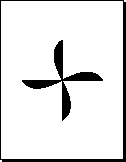
objPage.Canvas.AddCurve( 446, 296, 166, 496, 306, 596 );
objPage.Canvas.ClosePath();
objPage.Canvas.MoveTo( 106, 396 );
objPage.Canvas.AddCurve( 206, 256, 406, 536, 506, 396 );
objPage.Canvas.ClosePath();
objPage.Canvas.Fill();
In addition to Stroke and Fill methods, PdfCanvas also offers the FillStroke method which first fills a path and then strokes it.
4.3 Filling Rules
The Fill method used in the previous section paints the insides of all the subpaths of a current path, considered together. Any subpaths that are open are implicitly closed before being filled.
For a simple path, it is intuitively clear what region lies inside. However, for a more complex path -- for example, a path that intersects itself or has one subpath that encloses another -- the interpretation of "inside" is not always obvious. The path machinery uses one of two rules for determining which points lie inside a path: the nonzero winding number rule and the even-odd rule.
4.3.1 Nonzero Winding Number Rule
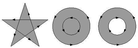
The nonzero winding number rule determines whether a given point is inside a path by conceptually drawing a ray from that point to infinity in any direction and then examining the places where a segment of the path crosses the ray. Starting with a count of 0, the rule adds 1 each time a path segment crosses the ray from left to right and subtracts 1 each time a segment crosses from right to left. After counting all the crossings, if the result is 0 then the point is outside the path; otherwise it is inside.
For simple convex paths, the nonzero winding number rule defines the inside and outside as one would intuitively expect. The more interesting cases are those involving complex or self-intersecting paths. For a path consisting of a five-pointed star, drawn with five connected straight line segments intersecting each other, the rule considers the inside to be the entire area enclosed by the star, including the pentagon in the center. For a path composed of two concentric circles, the areas enclosed by both circles are considered to be inside, provided that both are drawn in the same direction. If the circles are drawn in opposite directions, only the "doughnut" shape between them is inside, according to the rule; the "doughnut hole" is outside:
4.3.2 Even-Odd Rule
An alternative to the nonzero winding number rule is the even-odd rule. This rule determines the "insideness" of a point by drawing a ray from that point in any direction and simply counting the number of path segments that cross the ray, regardless of direction. If this number is odd, the point is inside; if even, the point is outside. This yields the same results as the nonzero winding number rule for paths with simple shapes, but produces different results for more complex shapes.
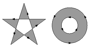
To fill a path using the Even-Odd rule, the Fill and FillStroke methods must be called with a True argument, as follows:
objPage.Canvas.FillStroke( true );
4.4 Managing Graphics State
The PdfCanvas object provides properties and methods to define the current graphics state which holds all major drawing parameters, such as the current stoking and filling colors, color space, line width, line join style, and others. Many graphics state parameters can be specified via their respective designated properties and methods, such as LineWidth, as well as the universal SetParams method.
4.4.1 Colors
The current stroking and filling colors are set via the SetColor and SetFillColor methods, respectively. Both methods accept three RGB color components in the range of 0.0 to 1.0. For example, the code
objPage.Canvas.SetFillColor( 1, 0, 0 );
sets the current stroking color to blue and filling color to red. Alternatively, the current colors can be specified via a parameter string passed to the SetParams method, for example:
Both the stroking and filling colors are black by default.
In addition to setting the stroking and filling colors, the SetColor and SetFillColor methods also set the current color space to RGB. To switch to the CMYK color space and set CMYK colors for the stroking and filling operations, the methods SetColorCMYK and SetFillColorCMYK methods should be used, respectively. These methods expect 4 arguments: cyan, magenta, yellow and black components.
As of Version 2.5, AspPDF supports many additional color spaces besides RGB and CMYK. Advanced color spaces are described in Chapter 15 - Color Spaces.
4.4.2 Line Width and Cap Style
The current line width is set via the LineWidth property which is set to 1 by default. A line width can be a fractional number. Alternatively, the line width can be specified via the SetParams method, as follows:
The Line Cap style specifies the shape to be used at the ends of open subpaths (and dashes, if any) when they are stoked. The Line Cap parameter can be set to one of three values:
Style 0: Butt cap. The stroke is squared off at the endpoint of the path. There is no projection beyond the end of the path. This is the default value.
Style 1: Round cap. A semicircular arc with a diameter equal to the line width is drawn around the endpoint and filled in.
Style 2: Projecting square cap. The stroke continues beyond the endpoint of the path for a distance equal to half the line width and is then squared off.
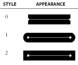
The current Line Cap parameter is specified via the LineCap property, or via the SetParams method as follows:
4.4.3 Line Join Style and Miter Limit
The Line Join style specifies the shape to be used at the corners of paths that are stroked. The Line Join parameter can be set to one of three values:
Style 0: Miter join. The outer edges of the strokes for the two segments are extended until they meet at an angle. If the segments meet at too sharp an angle (as defined by the miter limit parameter described below), a bevel join is used instead. This is the default style.
Style 1: Round join. A circle with a diameter equal to the line width is drawn around the point where the two segments meet and is filled in, producing a rounded corner.
Style 2: Bevel join. The two segments are finished with butt caps and the resulting notch beyond the ends of the segments is filled with a triangle.
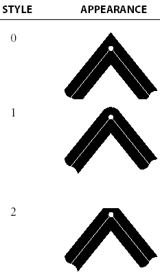
When two line segments meet at a sharp angle and mitered joins have been specified as the line join style, it is possible for the miter to extend far beyond the thickness of the line stroking the path. The miter limit imposes a maximum on the ratio of the miter length to the line width. When the limit is exceeded, the join is converted from a miter to a bevel. The ratio of miter length to line width is directly related to the angle alpha between the segments in user space by the formula
miterLength / lineWidth = 1 / sin( alpha / 2 )
The Line Join style and Miter Limit parameters can be specified via the LineJoin and MiterLimit properties, respectively, as well as the SetParams method, as follows:
The line dash pattern controls the pattern of dashes and gaps used to stroke paths. It is specified by a dash array and a dash phase. The dash array’s elements are numbers that specify the lengths of alternating dashes and gaps; the dash phase specifies the distance into the dash pattern at which to start the dash. By default, the dash value array is empty and dash phase is 0, which corresponds to a solid, unbroken line.
Dash array values and dash phase can only be specified via the SetParams method. The following five calls to the SetParams method produce patterns displayed below:
objPage.Canvas.SetParams( "Dash1=2; DashPhase=1" );
objPage.Canvas.SetParams( "Dash1=2; Dash2=1; DashPhase=0" );
objPage.Canvas.SetParams( "Dash1=3; Dash2=5; DashPhase=6" );
objPage.Canvas.SetParams( "Dash1=2; Dash2=3; DashPhase=11" );
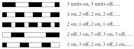
Starting with version 1.6.0.11, a line can be made solid via the syntax
4.5 Advanced Graphics State Issues
A transformation matrix specifies the relationship between two coordinate spaces. By modifying a transformation matrix, objects can be scaled, rotated, translated, or transformed in other ways.
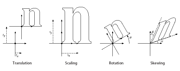
A transformation matrix in PDF is specified by an array of six numbers, [a b c d e f]. It can represent any linear transformation from one coordinate system to another. The most common types of transformation are translation, scaling, rotation and skew.
Translations are specified as [1 0 0 1 tx ty], where tx and ty are the distances to translate the origin of the coordinate system in the horizontal and vertical dimensions, respectively.
Scaling is obtained by [sx 0 0 sy 0 0]. This scales the coordinates so that 1 unit in the horizontal and vertical dimensions of the new coordinate system is the same size as sx and sy units, respectively, in the previous coordinate system.
Rotations are produced by [cos(alpha) sin(alpha) -sin(alpha) cos(alpha) 0 0], which has the effect of rotating the coordinate system axes by an angle alpha counterclockwise.
Skew is specified by [1 tan(alpha) tan(beta) 1 0 0], which skews the x axis by an angle alpha and the y axis by an angle beta.
To specify a transformation matrix, the PdfCanvas objects the method SetCTM which takes 6 numbers, a, b, c, d, e, and f, as arguments. By default, the current transformation matrix (CTM) is [1 0 0 1 0 0] which corresponds to identity transformation. Each call to SetCTM changes the CTM to the result of the multiplication of the current matrix with the new one.
A well-structured PDF document typically contains many graphical elements that are essentially independent of each other and sometimes nested to multiple levels. The graphics state stack allows these elements to make local changes to the graphics state without disturbing the graphics state of the surrounding environment.
The SaveState method pushes a copy of the entire graphics state onto the stack. The RestoreState method restores the entire graphics state to its former value by popping it from the stack. For example:
objPage.Canvas.SetColor( 1, 0.5, 0 );
objPage.Canvas.SetCTM( 1, 0, 0, 1, 10, 15 );
...
objPage.Canvas.RestoreState();
The graphics state contains a current clipping path that limits the regions of the page affected by painting operators. The initial clipping path includes the entire page.
A clipping path is created the same way as a regular path, but at the end instead of calling Fill, Stroke or FillStroke, you must call the Clip method (and optionally pass True if you want the path to be computed according to the Odd-Even rule, see Section 4.3 above). For example:
objPage.Canvas.MoveTo( 10, 10 );
objPage.Canvas.LineTo( 500, 10 );
objPage.Canvas.LineTo( 500, 500 );
objPage.Canvas.Clip();
...
<only the triangular area defined above will be affected>
...
objPage.Canvas.RestoreState();
4.6 Code Sample: Torus 3D
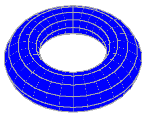
The following code sample uses basic graphics methods provided by the PdfCanvas object, such as SetParams and FillStroke, to create a 3D image of a torus.
The torus's surface is tiled with filled and stroked quadralaterals.
Several 3D graphics techniques are being employed by this code sample to build a projection of the torus at an angle, achieve a perspective effect and remove invisible surfaces.
Click on the links below to run this code sample:


